Loading manual…
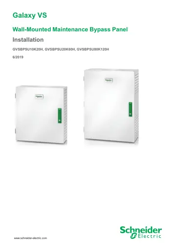
APC Maintenance Bypass Panel (GVSBPSU10K20H) user manual
- Type
- User manual
- Language
- English
- Pages
- 36
- Models
- GVSBPSU10K20H
Open PDFOpens the file on objects.icecat.biz.
Contents
- Galaxy VSp. 1
Wall-Mounted Maintenance Bypass Panel Installation GVSBPSU10K20H, GVSBPSU20K60H, GVSBPSU80K120H 6/2019 www.schneider-electric.com
- Important Safety Instructions — SAVE THESE INSTRUCTIONSp. 5
Wall-Mounted Maintenance Bypass Panel Important Safety Instructions — SAVE THESE INSTRUCTIONS Read these instructions carefully and look at the equipment to…
- Specificationsp. 9
Wall-Mounted Maintenance Bypass Panel Specifications NOTE: Maximum short circuit rating: 10 kA RMS symmetrical. NOTE: GVSBPSU80K120H can support a load of up…
- Installation Procedurep. 13
Wall-Mounted Maintenance Bypass Panel Installation Procedure Single System – Single Mains Simplified 1+1 Parallel System – Single Mains Single System – Dual…
- Mount the Maintenance Bypass Panel to the Wallp. 14
CAUTION RISK OF INJURY OR EQUIPMENT DAMAGE • Mount the maintenance bypass panel to a wall or a rack that is structurally sound and able to support the weight…
- Prepare the Maintenance Bypass Panel for Cablesp. 16
DANGER HAZARD OF ELECTRIC SHOCK, EXPLOSION, OR ARC FLASH Do not drill or punch holes with the gland plates installed and do not drill or punch holes in close…
- Remove the Neutral Jumper (Option)p. 17
Wall-Mounted Maintenance Bypass Panel Remove the Neutral Jumper (Option) NOTE: The neutral jumper makes a bolted connection of the neutral so that the neutral…
- Connect the Power Cablesp. 18
NOTE: For a simplified 1+1 parallel system, install the power cables from the two UPSs on the front and rear side of the busbar using the same bolt. 1. Connect…
- Connect the Signal Cables for Single Systemp. 21
Wall-Mounted Maintenance Bypass Panel Connect the Signal Cables for Single System NOTE: Route the signal cables separately from the power cables and route the…
- Connect the Signal Cables for Simplified 1+1 Parallel Systemp. 24
NOTE: The breaker indicator lights are supplied by UPS 1 and will only work while UPS 1 is powered. NOTE: The AUX switches are in optional parallel…
- Add Translated Safety Labels to Your Productp. 31
Wall-Mounted Maintenance Bypass Panel Add Translated Safety Labels to Your Product The safety labels on your product are in English and French. Sheets with…
- Final Installationp. 32
1. Close the inner door and fasten it with the screws. 2. Add labels to the breaker indicator lamps, the breakers, and the diagram label according to your…
- Blank Pagep. 34