Loading manual…
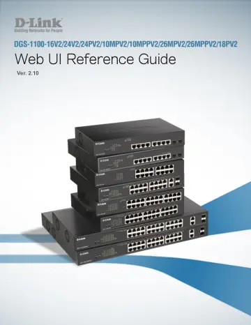
D-Link 26-Port PoE+ Gigabit Smart Managed Switch (DGS-1100-26MPV2) user manual
- Type
- User manual
- Language
- English
- Pages
- 136
- Category
- Network switches
- Models
- DGS-1100-26MPV2
Open PDFOpens the file on objects.icecat.biz.
Contents
- Introductionp. 14
This manual’s command descriptions are based on the software release 1.00. The commands listed here are the subset of commands that are supported by the…
- Audiencep. 14
This reference manual is intended for network administrators and other IT networking professionals responsible for managing the switch by using the Web User…
- Other Documentationp. 14
The documents below are a further source of information in regards to configuring and troubleshooting the switch. All the documents are available either from…
- Conventionsp. 14
Convention Description Boldface Font Indicates a button, a toolbar icon, menu, or menu item. For example: Open the File menu and choose Cancel. Used for…
- Notes, Notices, and Cautionsp. 15
Below are examples of the three types of indicators used in this manual. When administering your switch using the information in this document, you should pay…
- Product Introductionp. 16
Thank you and congratulations on your purchase of D-Link DGS-1100 Series Switch Products. D-Link's next generation DGS-1100 Series switches blends…
- Front Panelp. 16
diagnostic LEDs. The brand-new DGS-1100 series are born to be green by design of IEEE 802.3az Energy Efficient Ethernet compliant (abbreviated as EEE) and…
- Rear Panelp. 17
Figure 2-2 – DGS-1100-16V2 Rear Panel Power: The power port is where to connect the AC power cord.
- Front Panelp. 18
Figure 2-3 – DGS-1100-24V2 Front Panel Power LED: The Power LED lights up when the Switch is connected to a power source. Link/Act/Speed LED (Ports 1-24)…
- Rear Panelp. 18
Figure 2-4– DGS-1100-24V2 Rear Panel Power: Connect the supplied AC power cable to this port.
- Front Panelp. 19
Figure 2-5 – DGS-1100-24PV2 Front Panel Power LED: The Power LED lights up when the Switch is connected to a power source. Port LED Indicator(For PoE Model): A…
- Rear Panelp. 20
Figure 2-6– DGS-1100-24PV2 Rear Panel Power: Connect the supplied AC power cable to this port. CAUTION: This equipment can be connected only to PoE networks…
- Front Panelp. 20
Figure 2-7 – DGS-1100-10MPV2 Front Panel Power LED: The Power LED lights up when the Switch is connected to a power source. Port LED Indicator(For PoE Model)…
- Rear Panelp. 21
Figure 2-8– DGS-1100-10MPV2 Rear Panel Power: Connect the supplied AC power cable to this port. CAUTION: This equipment can be connected only to PoE networks…
- Front Panelp. 21
Figure 2-9 – DGS-1100-10MPPV2 Front Panel Power LED: The Power LED lights up when the Switch is connected to a power source. Port LED Indicator(For PoE Model)…
- Rear Panelp. 22
Figure 2-10– DGS-1100-10MPPV2 Rear Panel Power: Connect the supplied AC power cable to this port. CAUTION: This equipment can be connected only to PoE networks…
- Front Panelp. 23
Figure 2-11 – DGS-1100-26MPV2 Front Panel Power LED: The Power LED lights up when the Switch is connected to a power source. Port LED Indicator(For PoE Model)…
- Rear Panelp. 23
Figure 2-12– DGS-1100-26MPV2 Rear Panel Power: Connect the supplied AC power cable to this port.
- Front Panelp. 24
Figure 2-13 – DGS-1100-26MPPV2 Front Panel Power LED: The Power LED lights up when the Switch is connected to a power source. Port LED Indicator(For PoE…
- Rear Panelp. 25
Figure 2-14– DGS-1100-26MPPV2 Rear Panel Power: Connect the supplied AC power cable to this port. CAUTION: This equipment can be connected only to PoE networks…
- Front Panelp. 25
Figure 2-15 – DGS-1100-18PV2 Front Panel Power LED: The Power LED lights up when the Switch is connected to a power source. Port LED Indicator(For PoE Model)…
- Rear Panelp. 26
Figure 2-16– DGS-1100-18PV2 Rear Panel Power: Connect the supplied AC power cable to this port. CAUTION: This equipment can be connected only to PoE networks…
- Hardware Installationp. 27
This chapter provides unpacking and installation information for the D-Link Switch
- Step1: Unpackingp. 27
Open the shipping carton and carefully unpack its contents. Please consult the packing list located in the User Manual to make sure all items are present and…
- Packing contents of DGS-1100-16V2 /24V2 /24PV2/10Mp. 27
- Step2: Switch Installationp. 27
For safe switch installation and operation, it is recommended that you: Visually inspect the power cord to see that it is secured fully to the AC power…
- Desktop or Shelf Installationp. 27
When installing the switch on a desktop or shelf, the rubber feet included with the device must be attached on the bottom at each corner of the device’s base.…
- Rack Installationp. 28
The switch can be mounted in an EIA standard size 19-inch rack, which can be placed in a wiring closet with other equipment. To install, attach the mounting…
- Step 3 – Plugging in the AC Power Cordp. 29
Users may now connect the AC power cord into the rear of the switch and to an electrical outlet (preferably one that is grounded and surge protected). Figure…
- Power Failurep. 29
As a precaution, the switch should be unplugged in case of power failure. When power is resumed, plug the switch back in. Grounding the Switch This section…