Loading manual…
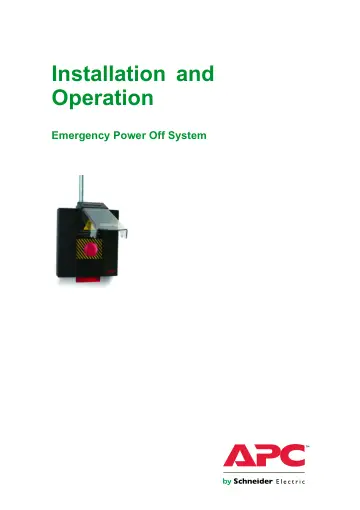
APC Emergency Power Off (EPO) (EPW9) user manual
- Type
- User manual
- Language
- English
- Pages
- 24
- Models
- EPW9
Open PDFOpens the file on objects.icecat.biz.
Contents
- IMPORTANT SAFETY INSTRUCTIONS SAVE THESE INSTRUCTIONSp. 5
This manual contains important instructions that should be followed during installation, operation, and maintenance of the EPO system
- Safety Instructions for North Americap. 5
WARNING: Only certified electricians may install the system and the wiring to the products IT controls. WARNING: Assembly has not been evaluated for emergency…
- Safety Instructions for Europe, Middle East, and Africap. 6
- Specificationsp. 7
Electrical Input/Output Voltage 24 VDC 48 VDC/240 VAC (External circuit) Current 1 A at 24 VDC 1 A at 48 VDC (External circuit) Frequency 50/60 Hz Circuits…
- Overviewp. 8
Emergency Power Off System The Emergency Power Off (EPO) System consists of one or more wall-mounted, push-button EPO boxes. Each EPO box provides a single…
- Emergency Power Off Systemp. 8
The Emergency Power Off (EPO) System consists of one or more wall-mounted, push-button EPO boxes. Each EPO box provides a single point of equipment shutdown…
- EPO Box Componentsp. 8
Flag 2 Button 3 Shield 4 Knockouts 5 Mounting holes 6 Blanking panels 7 Wire anchors 8 Auxiliary device terminal 9 Device terminal block 10 Cascading jacks 11…
- Installationp. 10
Prepare the EPO 1. Open the EPO System box by removing the screws on the side. Keep the screws for use after the system is installed. The box will not close…
- Prepare the EPOp. 10
1. Open the EPO System box by removing the screws on the side. Keep the screws for use after the system is installed. The box will not close securely without…
- Mount the EPO (Running Conduits or Cables Along the Wall)p. 10
1. Fasten four 6.35 mm (¼ in) screws through the four mounting holes at each corner of the EPO box and into the wall. 2. Run the conduits (or cables) for the…
- Mount the EPO (running conduits or cables behind the wall)p. 11
1. Install a junction box or a switch box behind the wall. The EPO box will fasten directly to the box. Use one of the options above. 990–1611C-001 Emergency…
- Connect Devices to the EPO Boxp. 13
Connect APC devices to terminals 1–8. Connect an auxiliary device to terminal 9. Connect only one 0.10–0.75 mm² (24–18 AWG) wire pair to each terminal block.…
- Mount Additional EPO Boxesp. 14
There are two alternatives for wiring additional EPO boxes. Either cascade the boxes only to wire devices to one box (see “
- Cascade Multiple EPO Boxesp. 14
“), or wire devices directly to each EPO box (see “Direct Wiring Alternative“). Cascade Multiple EPO Boxes When cascading EPO boxes, connect a wire pair from…
- Direct Wiring Alternativep. 16
If the APC devices are centrally located between exit doors, it may be more practical to run separate wire pairs from the devices to each EPO box. This wiring…
- Verify Connections at each EPO Boxp. 16
1. Verify that the wiring is correct before attaching critical load devices to your devices: A. With the devices powered ON, use a small tool to press each…
- Operationp. 18
Engage the System 1. Lift the shield on any of the installed EPO boxes and press the button. A red flag will drop down from the box, providing an easy visual…
- Engage the Systemp. 18
1. Lift the shield on any of the installed EPO boxes and press the button. A red flag will drop down from the box, providing an easy visual mark as to which…
- Reset the EPO Systemp. 18
1. Pull the button towards you (1) and push the flag up until it catches (2). Pulling the button does not bring power back to the connected equipment; it only…
- Reset the Equipmentp. 19
Apply power to the devices according to the procedures for each device. Note: Refer to the operation manual included with each device for specific instructions…
- Wiring Diagramp. 20
Emergency Power Off System Installation and Operation 990–1611C-001